SPD Mod to Get Kingston Fury DDR4 RAM Working with Dell's XPS 17 9710
When it comes to purchasing a computer, an upgrade to higher end parts during the ordering process usually entails a markup on those parts compared to what it would cost to buy directly from a manufacturer. For example, the cost of RAM (memory) or SSDs (storage) is often exorbitant compared to the price one could purchase it for directly from Samsung, Micron, etc. For the majority of buyers, the convenience of receiving a device with any desired upgrades out of the box may be worth the higher cost. However, as someone who enjoys tinkering with systems and machines, I generally resist paying for such upgrades if I know the task is within my capabilities to do myself. For a desktop, I more or less will only build them myself. However, a laptop is much more constrained, and there’s no other practical option than to purchase a pre-built from a company.
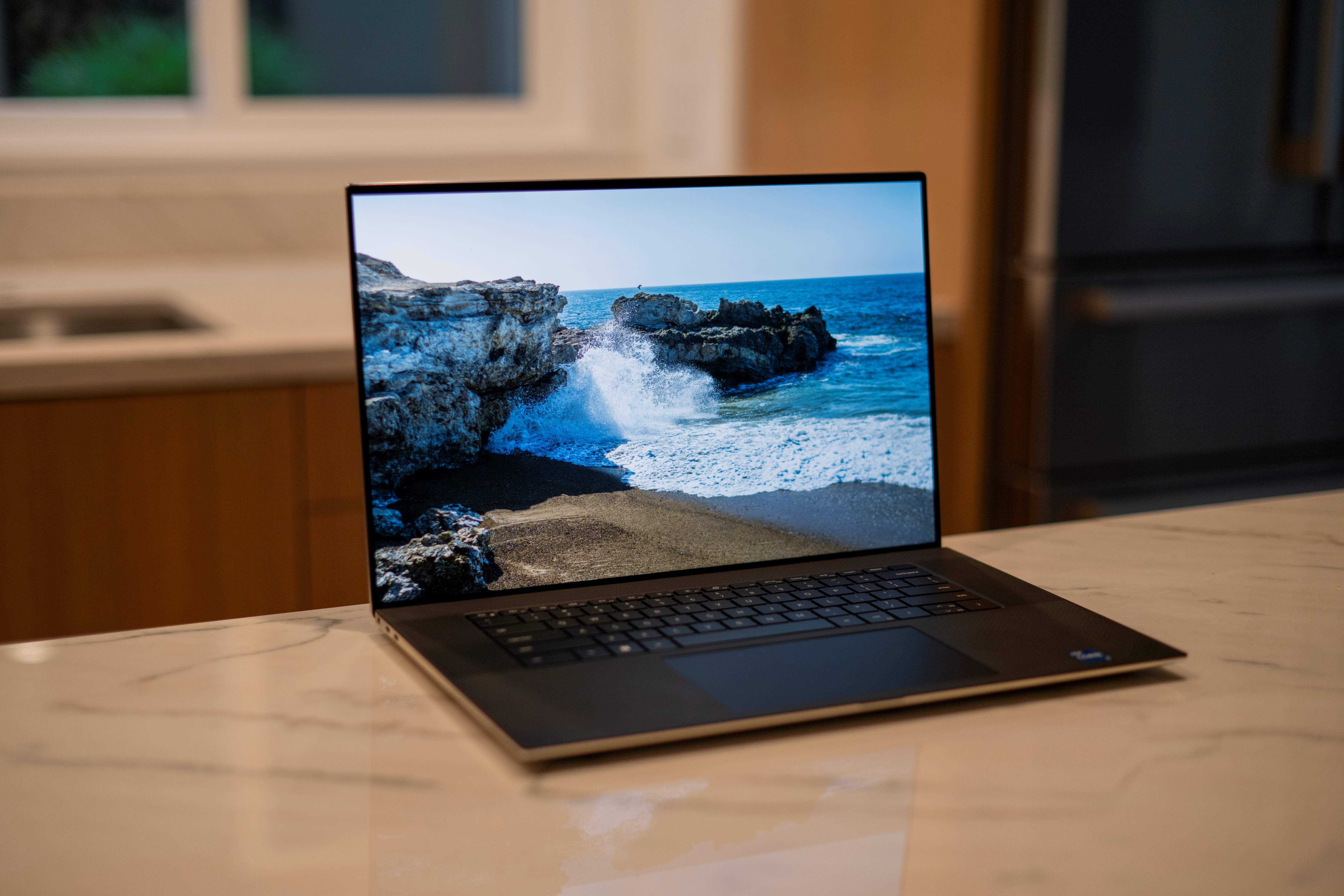
However, this does not mean that I want to pay for overpriced RAM or SSDs. It wouldn’t be an option for a system like Apple’s, as they solder the flash memory modules and ram chips directly to the main board for their Apple Silicon based computers, mandating the device be customized when ordering. In their laptops, Dell uses standard SO-DIMM modules for memory, and two M.2 2280 slots for storage. When in the market for a new laptop, I specifically chose a model that utilized standard parts that I could upgrade myself, while still maintaining a sleek form factor and engaging design to my liking. The Dell XPS 17 (9710) fit the bill. This is the second generation of the redesign, containing an 11th gen Intel processor that features the Willow Cove Core microarchitecture. I was particularly interested in this CPU generation as it is built on Intel’s 10nm process.
I ordered a machine towards the end of its model year during the final inventory sale. It had the right combination of specs that I could not change later (UHD+ touchscreen with Gorilla Glass, i7 11800H, Nvidia RTX 3060 6GB GPU, black keyboard), and more basic amounts of RAM (16gb) and storage (500gb PCIE Gen 4 M.2 SSD) that I planned to swap out from the get-go. When it arrived in the mail, I did an initial boot and verified it worked as expected. Good to go. Now on to taking it apart!
Initial Installation
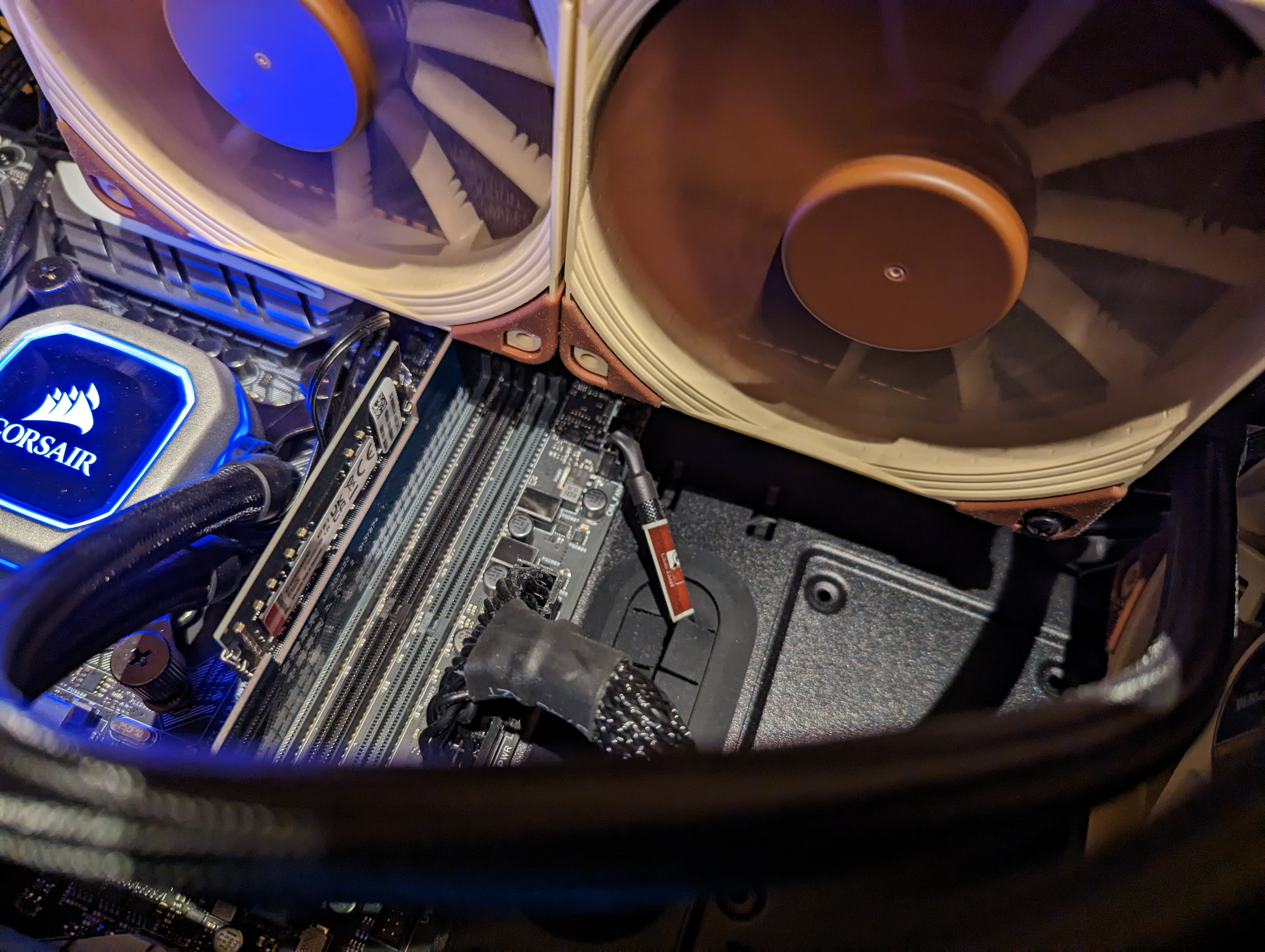
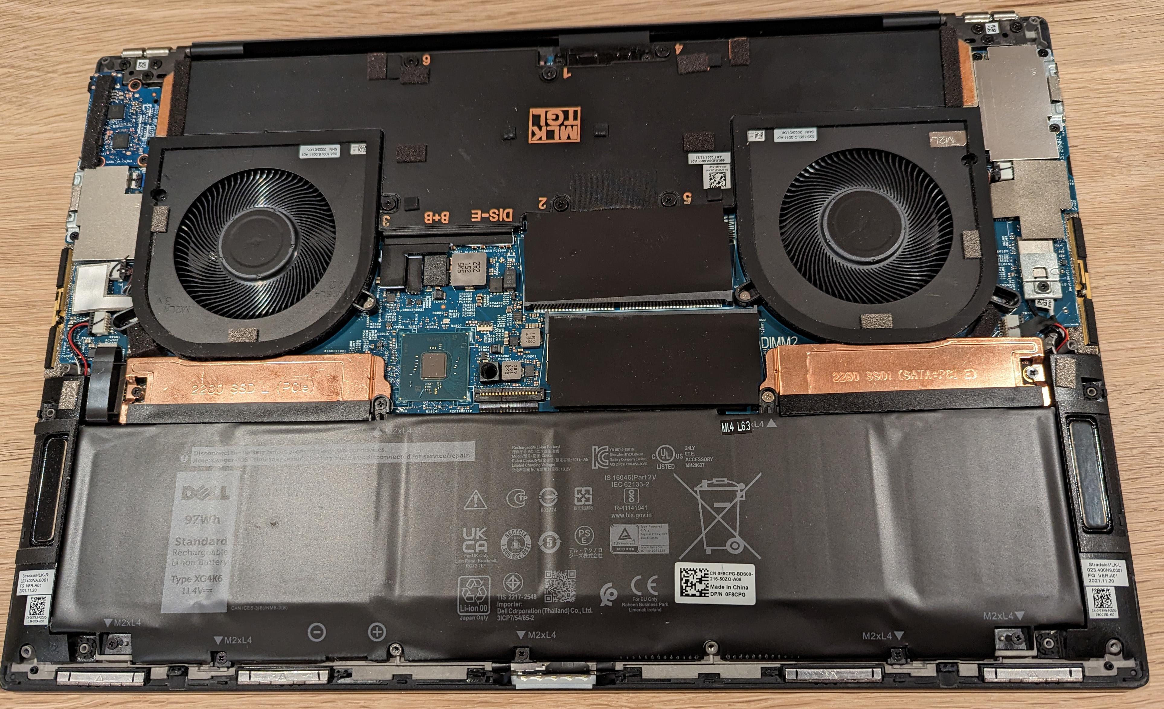 Let’s have a look at the internals. Taking the bottom cover off was slightly more laborious than expected: after removing all screws, the cover still required a plastic crow bar to pry it up at multiple spots around the chassis. A little bit of finger grease and it removed in due time! Overall, the layout appears typical of a modern laptop. Two fans at the upper corners, the main board in the center, and battery at the bottom. The 17 inch model includes a vapor chamber for improved CPU and GPU cooling compared to traditional heat pipes (not visible in this image). Of note are the two copper heatsinks for each M.2 SSD, and the two blank covers for the SO-DIMM RAM modules.
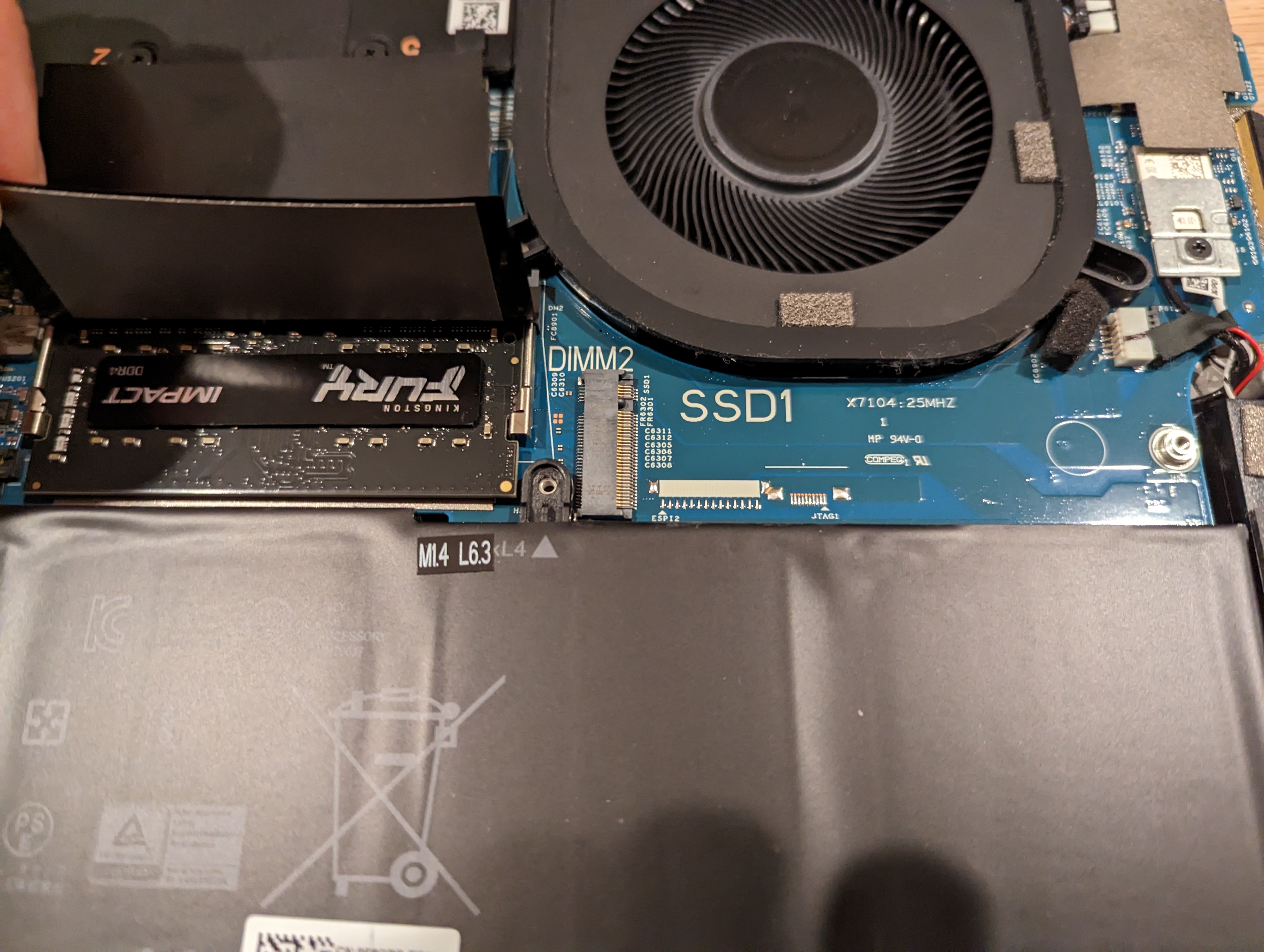 I further removed the SSD cover, factory SSD, and RAM, and replaced them for my own. For the third party RAM, I chose Kingston Fury Impact DDR4 3200 Mhz DIMMs. Kingston is a smaller, independent memory manufacturer, and they tend to support the DIY and tinkerer market. For the SSD, I grabbed a Samsung 980 Pro 1TB, which supports PCIE Gen 4 (Unfortunately, this generation dropped the MLC / 2 layer NAND found in the 970 series in favor of TLC / 3 layer for the 980 series, but this was now their flagship offering at the time).
Simple enough right? I put the cover back on, and it should boot!
Unfortunately, life is not so simple.
Power On
After pressing the power button, I was greeted by no POST screen. The power indicator light flashed a 2 amber and 5 white light code, which after perusing Dell’s documentation, means “invalid memory installed.” Well, great. Their suggested resolution was to either “reseat the memory” or “troubleshoot the memory further.” I probably should have checked this BEFORE reattaching the bottom cover. Oh well 😒
Back into the internals, the memory modules were properly and snugly seated in their respective slots. So “troubleshoot the memory further” seemed the path forward, and that is exactly what took place. After additional Googling, I was not the only one to have run across this problem with an XPS 17 9710 refusing to boot with Kingston’s Fury RAM. Luckily, enough discussion had taken place on various online forums that the community narrowed down the issue to Dell checking for the presence of an XMP profile on third party RAM, and if present, choosing to error instead of booting. There’s really no reason for this to exist in their firmware other than a massive bug, or purposefully wanting to deter users from installing third party memory. It’s true that I wouldn’t expect to overclock the RAM in this laptop, but all high performance memory stores an XMP profile as part of its SPD (Serial Presence Detect, more on this later) as they run above standard DDR specifications. Its presence does not mean the host computer must run the memory at a faster clock: Dell could choose to ignore it, as most motherboards do by default until you manually turn on XMP / overclocking. But, I suspect they ardently used the XMP profile as an “indicator” of “invalid memory.” Contacting support would not help. They would almost certainly point fingers that this third part ram in “incompatible” and that I should buy Dell RAM. No thank you.
What are the options?
As hinted at, one path forward would be to purchase official Dell RAM modules. This would be a last resort, and out of principal, I would almost refuse to take this approach. Another would be to find third party RAM without an XMP profile present, but this would entail purchasing yet another set of memory. Moreover, while perusing different discussions, a small set of users managed to get RAM with a factory XMP profile to work in the XPS 17 9710. With a slight modification to the DIMMs, zeroing out the XMP profile from the serial SPD contents, the laptop booted without an issue.
I already had the RAM, so why not try the last one?
The First Modification Attempts
A little bit of background on serial presence detect. This is a JEDEC standard protocol that allows a specific module installed in a computer to convey its timings, frequencies, manufacturer data, serial number, etc., which therefore enables the BIOS to read and accordingly program the memory controller and voltage regulator modules. Intel’s Extreme Memory Profile (XMP) is an extension of SPD that uses an set of higher bytes (0x176 - 0x255) to encode higher performance memory timings. For a particular DIMM to support SPD, it stores that information in an EEPROM that is attached to the SMBus of the motherboard.
With a little more research, modifying the SPD EEPROM would require a few stars to align. Firstly, the modules themselves would need to allow writes to the EEPROM chip in their end-user configuration. It’s set by the voltage applied to a WP (write protection) pin, so there’s no changing this unless I unsoldered the EEPROM from the PCB. I was hoping Kingston configured it in the allow mode (I later confirmed this to be true! Plus other people online had been successful). Next, the motherboard BIOS must allow writing to the SPD. Lastly, I would need a way to read and then modify the SPD information from user space. For the last part, recall that the EEPROM storing the SPD is on the SMBus (a variant of I2C), so a host operating system with SMBus controller support in the kernel and an EEPROM driver should enable access to the SPD from user space similar to an I2C device. Luckily, Linux + i2c-tools fit the bill! It even has support specifically to dump SPD information though decode-dimms.
Of the three major requirements, the last one I had a plan, the first one I had hope, and the second one: I took an “empirical” approach. Clearly, I could not use the XPS 17 to do this. It wouldn’t even let me boot, much less allow me to write to the memory’s SPD EEPROM. I was also working with laptop RAM i.e. SO-DIMM form factor, so without many options, I tried my old laptop. It was an MSI Prestige 15 that also utilized DDR4 SO-DIMMs. Searching online did not yield a clear answer as to whether its main board would allow writing to the EEPROM. However, this was the most immediately available avenue, and MSI is something of an enthusiast brand, so maybe they would allow users to mess with their memory, right?
Hint: No.
I again found myself opening up the the bottom of a laptop, slotting in the Kingston RAM, and hitting the power button. This time it POSTed at least! I loaded into a Ubuntu partition, and I figured I’d try to read and write to the SPD EEPROM. I found a python3 script on Github that attempts to make it easier to work with the SPD by reading its contents to a file (which I could modify), and writing a (the modified) file to the SPD EEPROM. Double checking the source code, it essentially opens a file descriptor on the EEPROM device and then utilizes fnctl to read to write to it. Makes sense if you were to ask me.
First, I read my RAM’s SPD information:
1
2
3
4
5
6
7
8
9
10
sudo ./spd-eeprom.py -r -d 1 -f out1
Reading from EE1004 SPD EEPROM: 0x51 on SMBus 0

SPD PAGE 0:
Reading at 0xff

SPD PAGE 1:
Reading at 0xff

Read done.
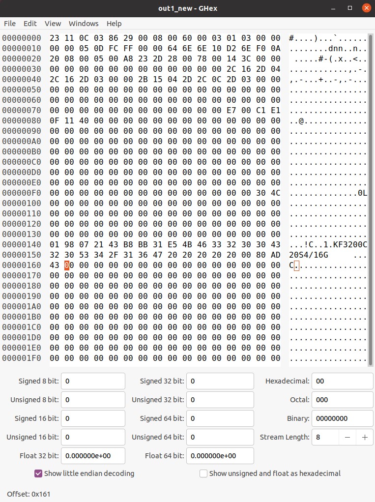
This read DIMM number 1 to the file out1, which contained the raw bytes, so I loaded it into a HEX file editor to see it cleanly and make the proper changes. If one of my coworkers had been the one taking this journey, he likely would have used VIM 😶.
I was presented with the following:
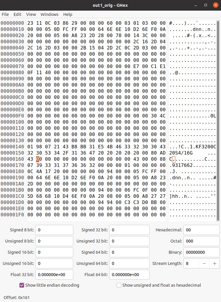
Now, to compare it to the table of designated fields for DDR4 SPD contents and the XMP profile on Wikipedia, bytes 0x161 - 0x1FF contained manufacturer specific data plus the information pertaining to the XMP profile. I zeroed all of it out for good measure, and saved a copy to a file for writing.
And now to execute that write:
1
2
3
4
5
6
7
8
9
10
sudo ./spd-eeprom.py -w -d 1 -f out1
Writing to EE1004 SPD EEPROM: 0x51 on SMBus 0

WARNING! Writing wrong data to SPD EEPROM will leave your system UNBOOTABLE!
Continue anyway? [y/N] y

SPD PAGE 0:
Writing at 0x00 (0x23)

Write failed.
That did not appear promising. Reading back the contents from the EEPROM, indeed nothing had changed. I also tried a different method with i2c-tools directly (I cover this more thoroughly later on). In short, even a more direct approach that tried to write to the exact byte locations also failed. My fear that MSI had not opened up write functionality to the SPD EEPROM was true after all. With further searching and now knowing this result, I found that it seems only ASUS unblocks the ability for writing functionality.
ASUS Desktop Motherboard, Yes Really
There were no other laptops with DDR4 SO-DIMM slots that I could readily try. The next DDR4 system that made sense was my desktop that I had built in 2015. This contained an ASUS Z170-DELUXE paired to an Intel Core i7-6700k. I found it somewhat amazing that an over 7 year old system was still compatible with RAM for a relatively recent laptop. The only difference was the form factor. I had to acquire (i.e. purchase) a DDR4 SO-DIMM to UDIMM adaptor to plug it in. Beyond that, it just plugged in.
At this point, in terms of time and cost spent, you may be wondering if I should have just bought the RAM upgrade when buying the laptop. Should is a relative term. The answer was still no for me 😉.
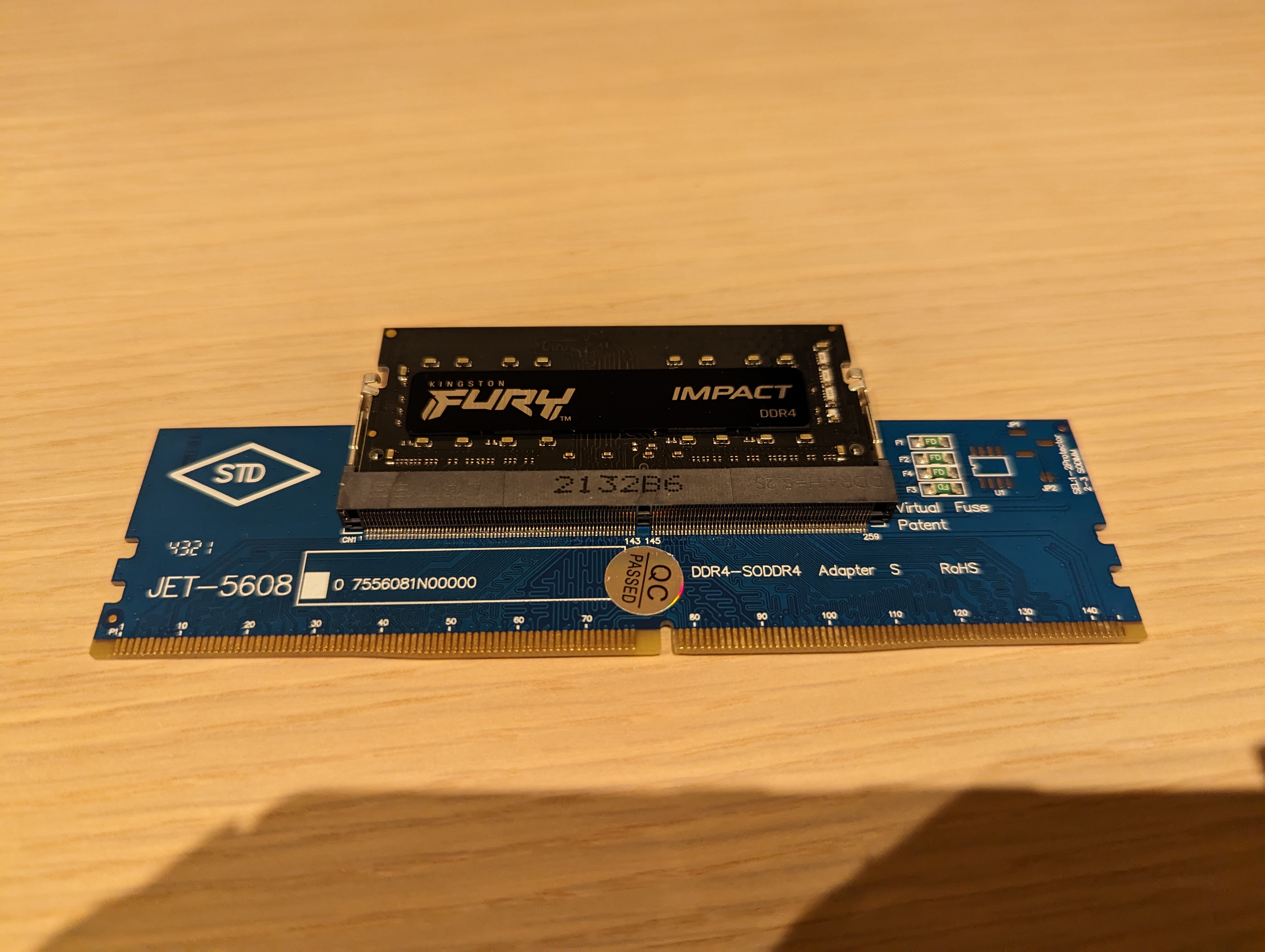
With the laptop memory seated in the converter, I installed the combo into the desktop.
Hopefully it would boot right up like the MSI, right? Of course not!
Different LEDs on the motherboard flashed, indicating that it attempted to boot a few times. Eventually, the Q-LED displayed an error code (or Q-Code as ASUS prefers to call it): 55, Memory not installed. Ok, so it wasn’t detecting the DIMM. I removed and reseated the SO-DIMM into the adapter and then adapter to the motherboard a couple of more times, after which I finally got it to POST!
Similar to before, I loaded up a Ubuntu partition, and I tried that Github tool again. Still no success. At this point, I figured I would just stick with i2c-tools directly moving forward as I had more confidence with that than an un-peer-reviewed repository which last saw attention a couple of years prior. However, i2c-tools also was unable to successfully write.
Something was missing. I could feel that I was so close, why was it still not working? Looking at the BIOS a bit more, even though ASUS allows SPD writes, one must enable this in the BIOS settings 🤦🏽♂️. A reboot, toggle, save, and one more restart, and that was enabled! At least I still had one more shot before I had to assume the RAM itself did not allow writing to the SPD EEPROM.
How I Actually Got Things Working
By now you’re probably thinking, “Ok Mark, you’ve brought me through ten-thousand different configurations that did not allow you to write to get this third party RAM working. What’s the solution? Also, you’ve been mentioning that you’ve been using i2c-tools. What does that specifically entail?”
Those are excellent questions! Let’s start with Linux’s built in i2c-tools. Compared to the Github script where I could easily specify a DIMM ID (1 or 2) and it would take care of the rest, I had to find the right addresses to use the the i2c-tools commands.
I started by loading the EEPROM and EE1004 modules into the kernel:
1
2
sudo modprobe eeprom
sudo modprobe ee1004
This allowed me to run decode-dimms that automatically finds where the SPD contents are and translates them:
1
2
3
4
5
6
7
8
9
10
11
12
13
14
15
16
17
18
19
20
21
22
23
24
25
26
27
28
29
30
31
32
33
34
35
36
37
38
39
40
41
42
43
44
45
46
47
48
49
50
51
52
53
54
55
56
57
58
59
60
61
62
63
64
65
66
67
68
69
70
71
72
73
74
75
76
decode-dimms
# decode-dimms version $Revision$

Memory Serial Presence Detect Decoder
By Philip Edelbrock, Christian Zuckschwerdt, Burkart Lingner,
Jean Delvare, Trent Piepho and others


Decoding EEPROM: /sys/bus/i2c/drivers/ee1004/0-0051
Guessing DIMM is in                              bank 2

---=== SPD EEPROM Information ===---
EEPROM CRC of bytes 0-125                        OK (0xE1C1)
# of bytes written to SDRAM EEPROM               384
Total number of bytes in EEPROM                  512
Fundamental Memory type                          DDR4 SDRAM
SPD Revision                                     1.1
Module Type                                      SO-DIMM
EEPROM CRC of bytes 128-253                      OK (0x4C30)

---=== Memory Characteristics ===---
Maximum module speed                             3200 MHz (PC4-25600)
Size                                             16384 MB
Banks x Rows x Columns x Bits                    16 x 17 x 10 x 64
SDRAM Device Width                               8 bits
Ranks                                            1
AA-RCD-RP-RAS (cycles)                           20-22-22-42
Supported CAS Latencies                          22T, 21T, 20T, 19T, 18T, 17T, 16T, 15T, 14T, 13T, 12T, 11T, 10T, 9T

---=== Timings at Standard Speeds ===---
AA-RCD-RP-RAS (cycles) as DDR4-3200              20-22-22-42
AA-RCD-RP-RAS (cycles) as DDR4-2933              19-21-21-39
AA-RCD-RP-RAS (cycles) as DDR4-2666              17-19-19-35
AA-RCD-RP-RAS (cycles) as DDR4-2400              15-17-17-32
AA-RCD-RP-RAS (cycles) as DDR4-2133              14-15-15-28
AA-RCD-RP-RAS (cycles) as DDR4-1866              12-13-13-25
AA-RCD-RP-RAS (cycles) as DDR4-1600              10-11-11-21

---=== Timing Parameters ===---
Minimum Cycle Time (tCKmin)                      0.625 ns
Maximum Cycle Time (tCKmax)                      1.600 ns
Minimum CAS Latency Time (tAA)                   12.500 ns
Minimum RAS to CAS Delay (tRCD)                  13.750 ns
Minimum Row Precharge Delay (tRP)                13.750 ns
Minimum Active to Precharge Delay (tRAS)         26.250 ns
Minimum Active to Auto-Refresh Delay (tRC)       45.750 ns
Minimum Recovery Delay (tRFC1)                   350.000 ns
Minimum Recovery Delay (tRFC2)                   260.000 ns
Minimum Recovery Delay (tRFC4)                   160.000 ns
Minimum Four Activate Window Delay (tFAW)        21.000 ns
Minimum Row Active to Row Active Delay (tRRD_S)  4.375 ns
Minimum Row Active to Row Active Delay (tRRD_L)  5.625 ns
Minimum CAS to CAS Delay (tCCD_L)                5.000 ns
Minimum Write Recovery Time (tWR)                15.000 ns
Minimum Write to Read Time (tWTR_S)              2.500 ns
Minimum Write to Read Time (tWTR_L)              7.500 ns

---=== Other Information ===---
Package Type                                     Monolithic
Maximum Activate Count                           Unlimited
Post Package Repair                              One row per bank group
Soft PPR                                         Supported
Module Nominal Voltage                           1.2 V
Thermal Sensor                                   No

---=== Physical Characteristics ===---
Module Height                                    30 mm
Module Thickness                                 2 mm front, 2 mm back
Module Reference Card                            A revision 2

---=== Manufacturer Data ===---
Module Manufacturer                              Kingston
DRAM Manufacturer                                SK Hynix (former Hyundai Electronics)
Manufacturing Location Code                      0x07
Manufacturing Date                               2021-W43
Part Number                                      KF3200C20S4/16G
We see a myriad of information about the DIMM, CAS latencies, corresponding memory timings, etc. I paid most attention to the first informational line:
1
Decoding EEPROM: /sys/bus/i2c/drivers/ee1004/0-0051
Pattern matching to the Github script output, both it and i2c-tools are using the EE1004 drivers to communicate with the EEPROM chip, which his located on the 0th bus at address 0x51.
I also checked this with i2cdetect -l which lists the installed buses:
1
2
3
4
5
6
7
8
sudo i2cdetect -l
i2c-3	i2c       	NVIDIA i2c adapter 5 at 1:00.0  	I2C adapter
i2c-1	i2c       	NVIDIA i2c adapter 1 at 1:00.0  	I2C adapter
i2c-6	i2c       	NVIDIA i2c adapter 8 at 1:00.0  	I2C adapter
i2c-4	i2c       	NVIDIA i2c adapter 6 at 1:00.0  	I2C adapter
i2c-2	i2c       	NVIDIA i2c adapter 2 at 1:00.0  	I2C adapter
i2c-0	smbus     	SMBus I801 adapter at f000      	SMBus adapter
i2c-5	i2c       	NVIDIA i2c adapter 7 at 1:00.0  	I2C adapter
Knowing the EEPROM would be on the SMBus, this also confirmed it would be on i2c-0.
From there, we can have it list the devices (via their associated addresses) on that bus:
1
2
3
4
5
6
7
8
9
10
sudo i2cdetect -y 0
     0  1  2  3  4  5  6  7  8  9  a  b  c  d  e  f
00:          -- -- -- -- -- 08 -- -- -- -- -- -- --
10: -- -- -- -- -- -- -- -- -- -- -- -- -- -- -- --
20: -- -- -- -- -- -- -- -- -- -- -- -- -- -- -- --
30: 30 -- -- -- -- 35 -- -- -- -- -- -- -- -- -- --
40: -- -- -- -- 44 45 -- -- 48 -- -- -- -- -- -- 4f
50: -- 51 -- -- -- -- -- -- -- -- -- -- -- -- -- --
60: -- 61 -- -- -- -- -- -- -- -- -- -- -- -- -- --
70: -- -- -- -- -- -- -- --
Recall we were looking for a device at 0x51, and it was there! Next, I used i2cdump to get the contents of the SPD at the EEPROM at 0x51.
1
2
3
4
5
6
7
8
9
10
11
12
13
14
15
16
17
18
19
sudo i2cdump -y -f 0 0x51
No size specified (using byte-data access)
     0  1  2  3  4  5  6  7  8  9  a  b  c  d  e  f    0123456789abcdef
00: 00 00 00 00 00 00 00 00 00 00 00 00 00 00 00 00    ................
10: 00 00 00 00 00 00 00 00 00 00 00 00 00 00 00 00    ................
20: 00 00 00 00 00 00 00 00 00 00 00 00 00 00 00 00    ................
30: 00 00 00 00 00 00 00 00 00 00 00 00 00 00 00 00    ................
40: 01 98 07 21 43 b8 bb 31 e5 4b 46 33 32 30 30 43    ???!C??1?KF3200C
50: 32 30 53 34 2f 31 36 47 20 20 20 20 20 00 80 ad    20S4/16G     .??
60: 43 00 00 00 00 00 00 00 00 00 00 00 43 00 00 88    C...........C..?
70: 07 39 33 31 37 36 36 32 00 00 00 01 00 00 00 00    ?9317662...?....
80: 0c 4a 17 20 00 00 00 00 00 94 00 00 05 fc ff 00    ?J? .....?..??..
90: 00 64 6e 6e 10 d2 6e f0 0a 20 08 00 05 00 a8 23    .dnn??n?? ?.?.?#
a0: 2d 00 00 00 00 00 00 00 00 00 00 00 00 00 00 00    -...............
b0: 00 00 00 00 00 00 00 00 94 00 00 06 fc 0f 00 00    ........?..???..
c0: 5d 68 68 10 d4 6e f0 0a 20 08 00 05 00 a8 27 27    ]hh??n?? ?.?.?''
d0: 00 00 00 00 00 00 00 00 94 94 00 c3 c3 d0 bb 00    ........??.????.
e0: 00 00 00 00 00 00 00 00 00 00 00 00 00 00 00 00    ................
f0: 00 00 00 00 00 00 00 00 00 00 00 00 00 00 00 00    ................
In comparison to the screenshot of the entire SPD contents above, we only see the highest 256 bytes of the EEPROM. I learned later that DDR4 includes a “nonstandard” ee1004 type with two pages on the device at 0x51, and additional addresses at 0x36 and 0x37 to select with page to work with. Luckily, the chip was already set to the second page that I wanted to modify.
From there I used i2cget and i2cset to read and write to specific addresses within the EEPROM.
1
2
3
4
5
6
7
8
9
10
sudo i2cget -y -f 0 0x51 0x6c
0x43

sudo i2cget -y -f 0 0x51 0xd9
0x94

sudo i2cset -y -f 0 0x51 0x6c 0x00

sudo i2cget -y -f 0 0x51 0x6c
0x00
The first two commands read bytes 0x6c and 0xd9 of the second page (i.e. 0x16c and 0x1d9 of the entire EEPROM). Next, I overwrote the value at 0x6c to 0x0, and lastly confirmed that this stuck!! I could have written a script to zero out the remaining bytes I wanted to, but for the time required to invest in that just for the 20 or so bytes did not seem necessary. I repeated the i2cset command for all remaining non-zero values greater than 0x6c.
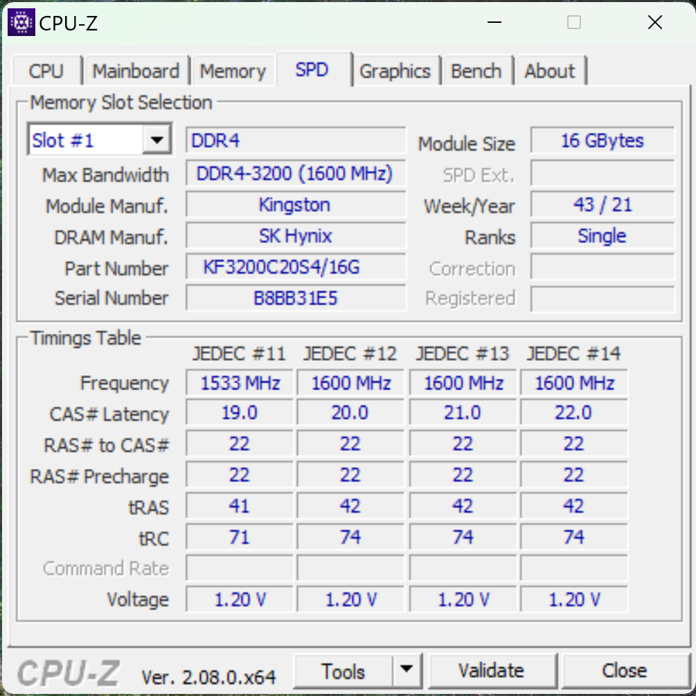
From there it was straight forward! I finished the first DIMM, then installed the second (I only had one adapter, otherwise could have worked on both at the same time), and modified its SPD contents too. Not long after, I installed both SO-DIMMs to the slots in the XPS 17, and it booted with no issues! How’s that for “invalid” memory?
Here’s a CPU-Z screenshot showing the memory working!
And the validation: link
Thanks for reading this post! Hopefully it helps if you’re trying to get some third part RAM to work in a Dell XPS laptop. I definitely learned a ton going through it, and I am excited that I was able to tinker with the hardware to finally get it to function 🦜.